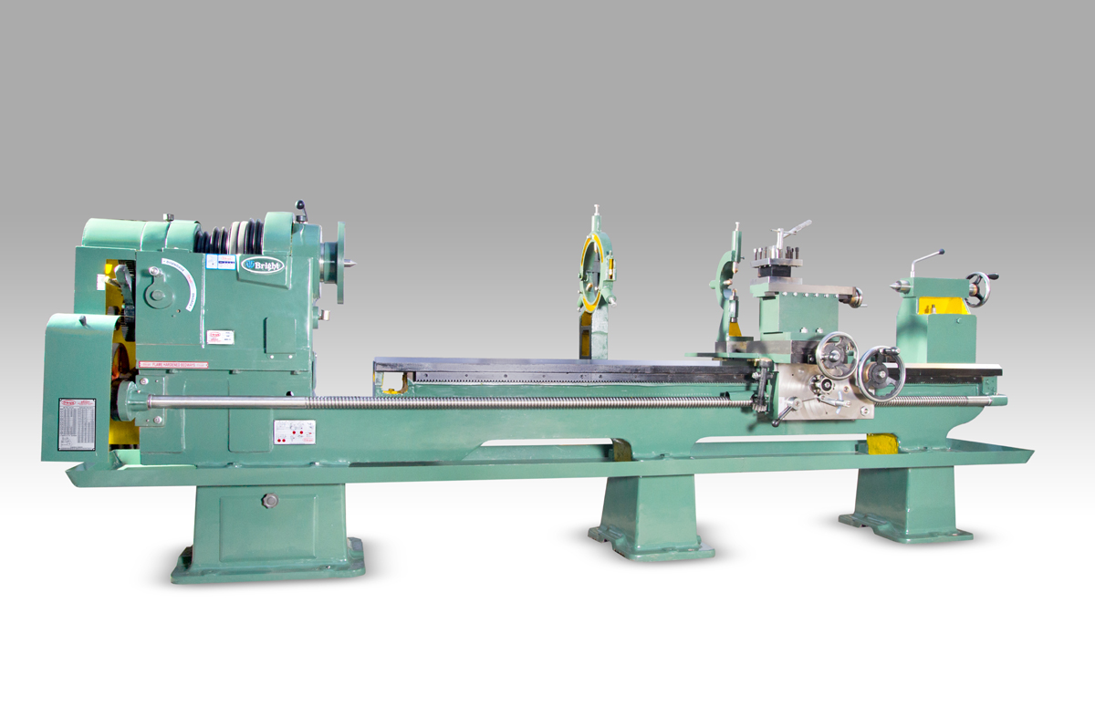
CYLINDRICAL GRINDING MACHINE
Quick ContactCylindrical Grinding Machines are special machines that are used for the final machining process for getting extra finishing and most accurate sizes of cylindrical parts.these are providing with a pair of two grindig wheel.
Head Stock:-The Wheel head is made of good quality graded cast iron material and it is well machined,it is completely oil bath,The spindle is made good alloy steel ,fully heat treated and grounded,it runs on best quality bearing ,bushes where it requires.
Tail Stock:- the tailstock is made of good quality graded cast iron material and it is well machined,maintained its centre with high accuracy to getting perfect grinding.tailstock spindle is made good alloy steel ,fully heat treated and grounded,
Wheel Head:- Thisi wheel head is mounted on the cross slide. It moves vertically so that the depth of cut can be fed by the cross-feed handwheel or via a power source,The cross-feed hand wheel is employed to position the wheel head , determining the depth of cut in the workpiece. Working Table. Sitting on guideways that enable ...
Grinding Wheel:-Grinding or Abrasive wheel is our main tool used here to remove the unwanted material from the workpiece to get desired smoothness and surface finish.
Work Table:-Normally, the workpiece is fastened to the work table of the grinder by a magnetic chuck, specialized vices, or vacuum chucks for nonmagnetic materials. The workpiece is fixed in the work table. And tool which is the grinding wheel is also fixed in the tool holder section. Now with the help of the traversing
Standard Accessories
- Coolant Pump with Tank
Grinding Wheel with Flange and Flange Puller
Chuck plate
Carbite Cipe Dead Centre 2 Nos.
Dressing tool Holder
Testing Bar
Toolkit
Lubrication oil pump
Turcite – B slide way
Safety Guards
Extra Accessories
- Internal Attachment
Wheel Balancing Stand
Wheel Balancing Mandrel
DRO
Steady rest
Follow rest
Spare Wheel flange
Magnetic separator
Anti vibration mount
Radius dresser
Carrier plate
Two speed motor
AC Drive For Workhead
Cartige Size Wheel Spindle
Specification
| Model | BG-1/CYL | BG-2/CYL | BG-3/CYL | BG-4/CYL |
|---|---|---|---|---|
| Max.Distance Between Centers | 300(11¾ inch) | 450(17¾ inch) | 600(23½" inch) | 1000(39¼" inch) |
| Max.Grinding Length in mm | 300(11¾ inch) | 450(17¾ inch) | 600(23½" inch) | 1000(39¼" inch) |
| Height Of Centre in mm | 115(4½" inch) | 115(4½" inch) | 115(4½" inch) | 170(6½" inch) |
| WHEEL HEAD | ||||
| Max.Grinding Wheel Dia in mm | 300(11¾ inch) | 350(13¾" inch) | 350(13¾" inch) | 500(19½" inch) |
| Max.Width oF Wheel in mm | 25 | 25 | 25 | 25 |
| Bore Of Grinding Wheel in mm | 127(5" inch) | 127(5" inch) | 127(5" inch) | 203(8" inch) |
| R.P.M. Of Grinding Wheel | 2000 | 1900 | 1900 | 1100 |
| Required Elect.Motor-H.P. | 2 H.P. | 2 H.P. | 2 H.P. | 3 H.P. |
| WORK HEAD | ||||
| Swivel Range in Degree | 45 Degree | 45 Degree | 45 Degree | 45 Degree |
| Morse Taper Of Spindle | MT/3 | MT/3 | MT/3 | MT/3 |
| No.Of Speed | 3 | 3 | 3 | 3 |
| Required Elect.Motor-H.P. | 0.5 H.P. | 0.5 H.P. | 0.5 H.P. | 0.5 H.P. |
| Total Weight in kg( Approx.) | 1000(1 M.T.) | 1200(1.2 M.T.) | 1500(1.5 M.T.) | 1800(1.8 M.T.) |

